In this article
Vision System Overview
Tascus supports integration with industrial vision systems to automatically inspect components and verify quality. This article outlines how to configure Sensopart VISOR and Keyence IV2 vision systems to work with Tascus.
Supported Vision Systems
Brand | Models |
|---|---|
Keyence | IV2 |
Sensopart | All models via TCP connection |
Sensopart Vision System Setup
Camera Configuration
Use SensoFind to locate the camera on your network. Double-click the device to open its configuration in Sensopart VISOR software.
Make a note of the camera’s IP Address – you’ll need this for Tascus setup.
Make a note of the camera's IP Adress, as you'll need to enter this into Tascus later.

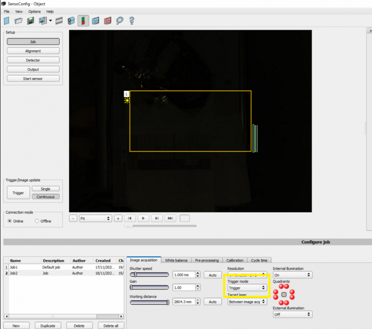
Job Configuration
Select the Job tab.
Set Trigger Mode to
Trigger.
This ensures the camera captures an image only when triggered by Tascus (not continuous capture).
Alignment & Detectors
Use the Alignment and Detector tabs to set up your vision inspection based on your application (e.g. barcode reading, pattern matching, presence detection).
Output Configuration
This is where you configure how the camera will communicate to Tascus.
Interfaces Tab
Enable the Ethernet ASCII interface with the following settings:
Setting | Value |
|---|---|
IN Port | 2006 |
OUT Port | 2005 |
ASCII Enabled | ✅ |
Logical Outputs | 0 |

Telegram Tab
This defines the message sent to Tascus when a job is triggered:
Setting | Value |
|---|---|
Start |
|
Trailer |
|
Format |
|
Payload | Add “Overall Result” for every detector in the job |
The telegram string will look like:
sPFPPPFt→ Fail (contains F)sPPPPPPt→ Pass (only P’s)st→ Fail (no P found)
Important: All detectors must be included in the payload, as there is no single overall job result.

5. Tascus Configuration
Go to Devices > Vision System > Config.
Set values as follows:
Setting | Value |
|---|---|
Vision System |
|
IP Address | Camera’s IP (from SensoFind) |
Ports |
|
Delay (ms) | Optional (typically 100–200) |

Camera Image Display
Images can be displayed as the raw image acquired by the camera, or via a web browser with the overlaid icons

Use the following url to display all overlay icons
monitor/image/live-any/overlay-all/1/errorhighlight
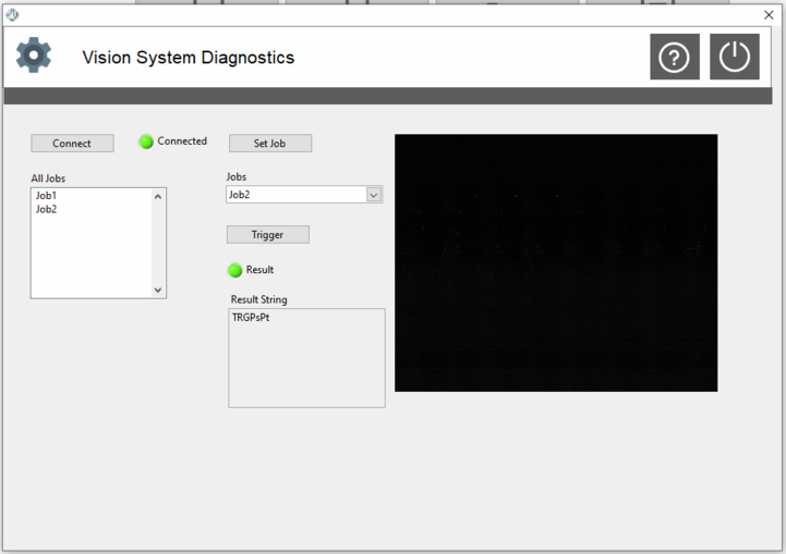
Click Vision System > Diagnostics to test the connection and trigger jobs.
Keyence IV2 Setup
For Keyence IV2 systems, communication is typically done through:
Discrete I/O (recommended for simple pass/fail integration)
Ethernet/IP or TCP (advanced models only – contact us for support)
1. Camera Configuration
Use the IV2-Navigator software to create and save jobs.
Set the External Trigger mode so the camera is triggered by Tascus via digital I/O.
Configure Output 1 or Result Output to send a Pass/Fail signal.
2. Tascus Setup for Digital I/O
If using a digital I/O module (e.g. Wago, National Instruments):
Configure a Digital Output in Tascus to trigger the camera.
Configure a Digital Input to read the result:
High= PassLow= Fail (or vice versa, depending on your IV2 configuration)
Use the Digital IO Step in your production sequence to:
Send the trigger signal
Wait for the result signal
Record pass/fail outcome
🧪 Diagnostics & Troubleshooting
Use the Diagnostics tab in Tascus to:
Test communication
Trigger a camera
View received messages (for ASCII setups)
Verify I/O status (for digital setups)
📎 Related Articles
Vision System step